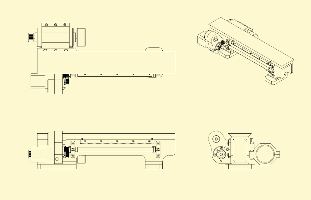
Description:
The bed is constructed from a stress-relieved steel tube. Steel reinforcements are welded into the tube to increase the machines stiffness. A cast iron way is bonded and fastened to the tube, acting as the main bed way of the machine. The tube is then filled with an epoxy granite. There are several accessories to be machined like:
- The leadscrew and bearing blocks
- Motor mount for the geared stepper powering the leadscrew and a rotary encoder to monitor the leadscrews speed relative to the spindle
- A modified stock rack gear
- A motor mount and belt tensioning assembly for the DC spindle drive motor
- Several plastic covers removed from the view above
Main Design and Manufacturing Considerations:
- Design bed to reduce displacement under loading conditions specific to a turning machine.
- Ensure that vibrations from normal operation are properly damped to reduce irregularities in work piece surface finish.
- Affix dovetail way to bed in such a way that the bed responds to loading as single cohesive beam.
- Ensure the machine base does not have a resonance frequency similar to those produced in turning machine operations.
- Ensure that all accessory features that interact with the carriage are positioned properly relative to the bed way in order to avoid binding or improper gear mesh.
- Produce a machine way with a small Rz value to mitigate rapid wear.
- Produce a machine way whose profile does not deviate from nominal more than .001″ over the 15″ length of the machine.
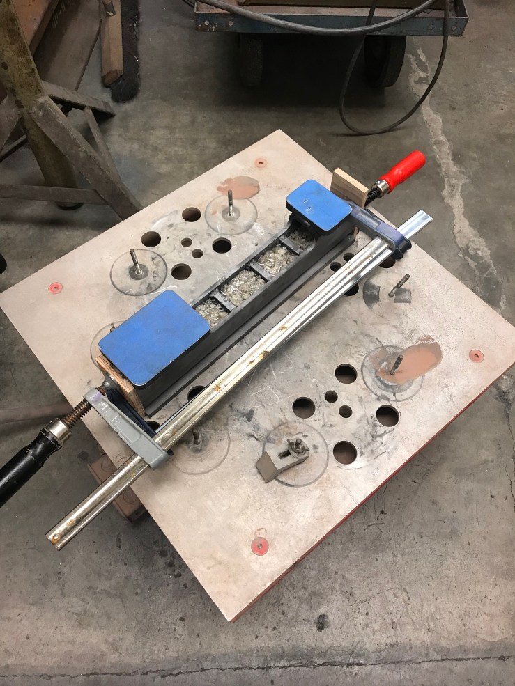 The epoxy granite in this machine should dampen vibration significantly better than cast iron. The epoxy granite is composed of 4 different particulate sizes ranging from dust to .375″ chunks. It was surprisingly difficult to source granite aggregate, so I broke up large blocks of granite counter top on the loading dock with a cold chisel and sorted the aggregate using mesh sieves. By weight my mixture is about 10-12% epoxy, and filled the voids nicely. I sprayed fastener with mold release and coated them with wax to fill some of the void and screwed them into all the holes on the bed to prevent epoxy from running out. I also have wood clamped on the ends to prevent the EG from running out of the cavity below the headstock as there is no welded in reinforcement to contain the mixture as it set. I also vibrated the EG as it set hoping to remove any air bubbles and to help level it off.


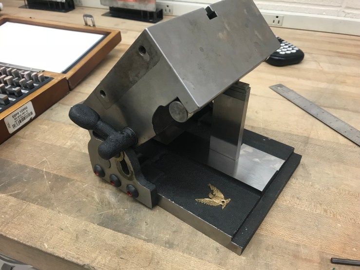
I could then square up the way relative to the rest of the bed. If the dovetail profile doesn’t run parallel to the front face of the lathe, there would be a large misalignment between the carriage and the rack gear and lead screw on the bed which in turn would cause improper gear mesh of the rack or binding of the lead screw. Instead of trying to locate the way blank relative to the bed with pins, I figured it would be easier to bond and fasten the blank oversize and mill/grind it to final dimension as an assembly.
Although the surface finish on the dovetail flanks was exceptional, I was worried that it still might have a larger Rz value inherent to milling whose peaks would wear faster then on a ground surface.I also hoped to fine tune dovetail profile on the grinder where I could achieve a much higher level of precision considering the accuracy of this machine is dependent almost totally on the accuracy of the main way, and the spindle.

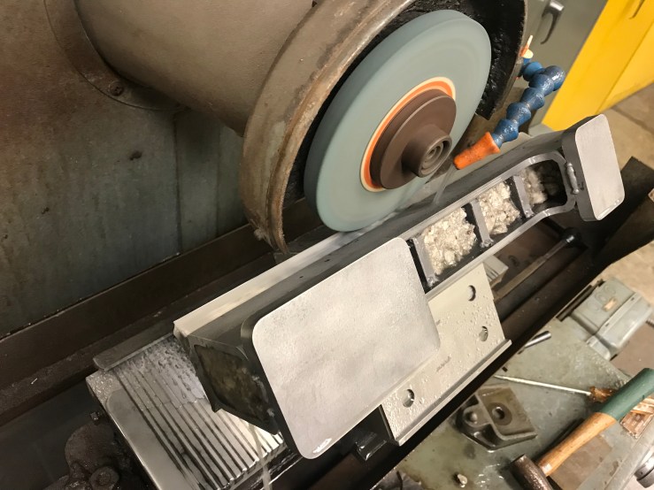
I ground the top surface first which I’ll then use as a reference surface when grind the side flanks. I then set a sin magnet chuck with a gage block stack. I then ground both dovetail flanks. All the cast iron grinding was done with a rough-dressed 60 grit silicon carbide wheel. I would’ve liked a coarser grit wheel, but I only needed to take off ~.002″ from all the surfaces so the wheel didn’t load up too quickly.
I was able to measure <= .0005″ out of parallelism on the dovetail flanks which I’m pretty pleased with. If those surfaces were misaligned enough the saddle gib would not be able to compensate for the taper between the the saddle/way and the carriage would rock under loading.

The finish speaks for itself.


While I waited for the cast iron blank that would soon form the headstock to arrive I machined the motor mount and belt tensioning assembly. I drilled the holes in the motor clamp and the mounting bracket for the sliding pins simultaneously to ensure that the pins wouldn’t bind along the travel. I also reamed the cast iron as it’s acting as a plain sleeve bearing as the belt starts to reach close to full tension.
