CMS is one of the two large general-use detectors on the LHC at CERN in Geneva Switzerland. There is currently a re-design in place to upgrade the detector for higher energies. Cornell is one of the U.S. leaders on the mechanics side of the inner most detector. I work as a design engineer in the mechanics group.
This project is still deeply in the R&D phase and most of the information associated with the project is still confidential. I specifically own two one-assembly on the mechanics team that I’ve been given permission to share general information about, along with a couple snapshots and assembly drawings. One of the sub-assemblies is a scratch, from problem statement design, that has taken on the large majority of my time. I will be ramping up the second in the fall.
Page Overview
Bullets below are linked to locations in the page. You may need to scroll up slightly to see the heading when using these, WordPress page linking is less than optimal…
- Quick Description
- Modeling of external loading
- Symoblic beam solver (MATLAB script) used to evaluate indeterminate beams using superposition
- Reference surfaces and issues associated with thermal cycling
- Force results generated from script
- Brute force spring optimization
- Understanding system sensitivity to expansion opposed friction
- Quadratic parameterization of roller contact force distribution and evaluation of contact stress
- Small design change — big feature control win
- Statics based parametric optimization
- TODO
- Cool photos of older version ANSYS results and assembly drawings
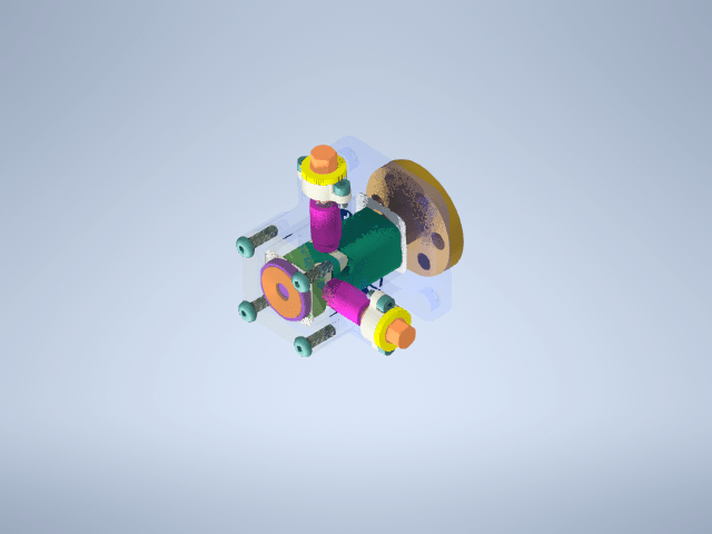
Owned Sub-Assembly “XYZ-Slider”
The inner most detector consists of a long (3 meter) structural housing whose job is to act as a mounting point for the physics sensors and carry the weight load of the various cooling and electrical connections that run to the physics sensors. The combination of the structural components, sensors, and cooling and electrical services is called the “inner-detector” or “service cylinder”. The absolute position of the sensors relative to some reference surface in the collision chamber has to be known to a high degree of accuracy to ensure the validity of the collision measurements. Not only is the position critical, but also the alignment of the detector relative the beamline.
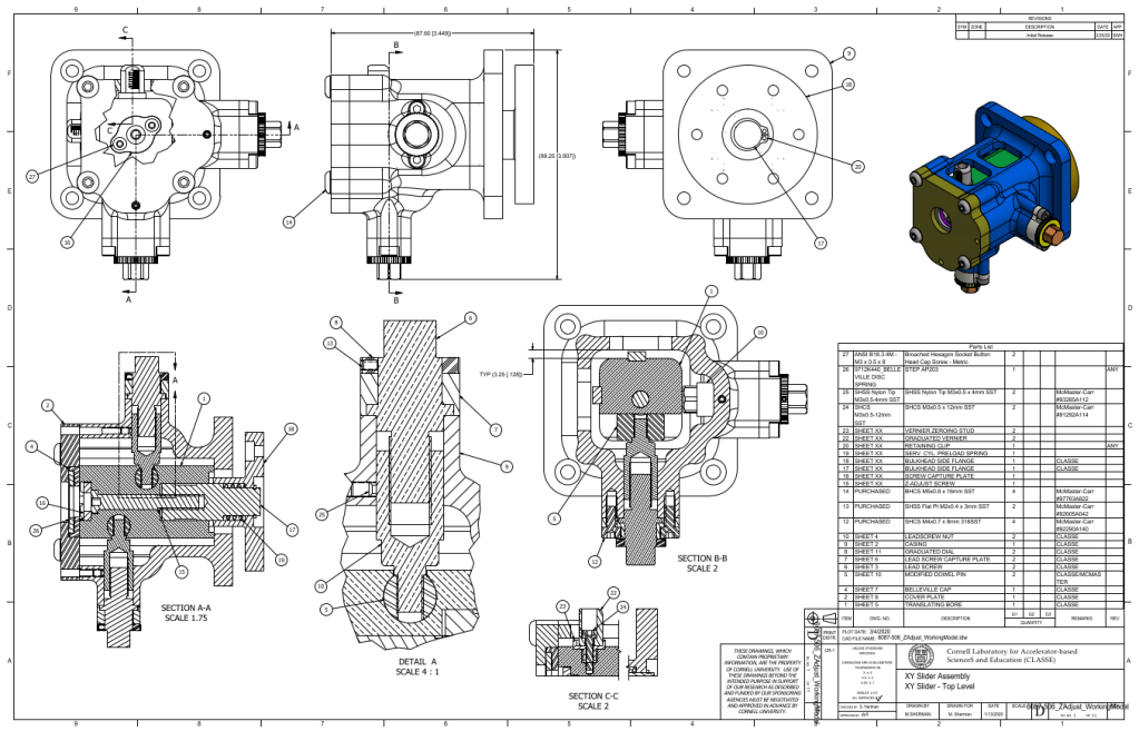
I am responsible for the complete design, analysis and manufacture of this assembly including the production of manufacturing drawings and their accompanying GD&T tolerances and tolerance stacks. My design is scratch from a problem statement. I am also responsible for designing testing tooling and test plans to evaluate the lifetime of the mechanism. A very rough outline of requirements which will be expanded upon in the following write-up is given below.
- Equilibrates the moment (210 Nm!) and transverse loading (615N) from the unsupported section of the inner-detector by coupling it to a more exterior bulkhead
- Allows for alignment of the detector back-end relative to the beam line (in plane, X, Y) with a resolution of 25-75 microns and a travel of +/- 3mm
- All for consistent biasing of the detector against a reference surface while allowing for virtually friction-less axial expansion (negative CTE) during cool down between 23C and -50C.
- Operate without any liquid lubrication or grease, as the high radiation destroys the different lubrication components. Either self-lubricating materials, without any sensitive impregnated particulates must be used, or just simply graphite powder
- Provide reliable feedback to an operator or technician whose view of the XYZ-Slider is extremely limited
- Additionally, the assembly is heavily constrained by its physical envelope and minimal accessibility and must be purely mechanical
Modeling External Loading
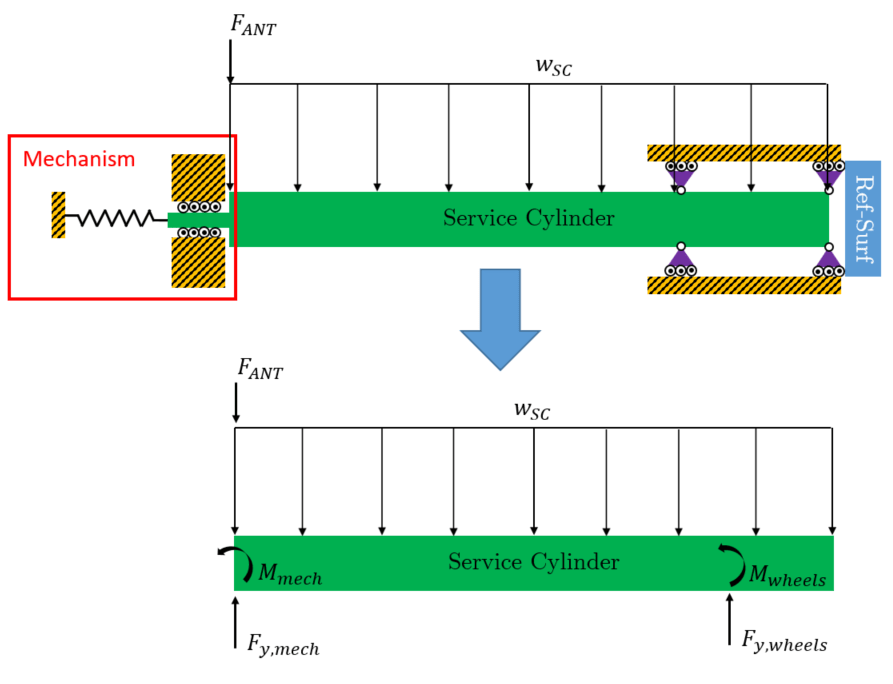
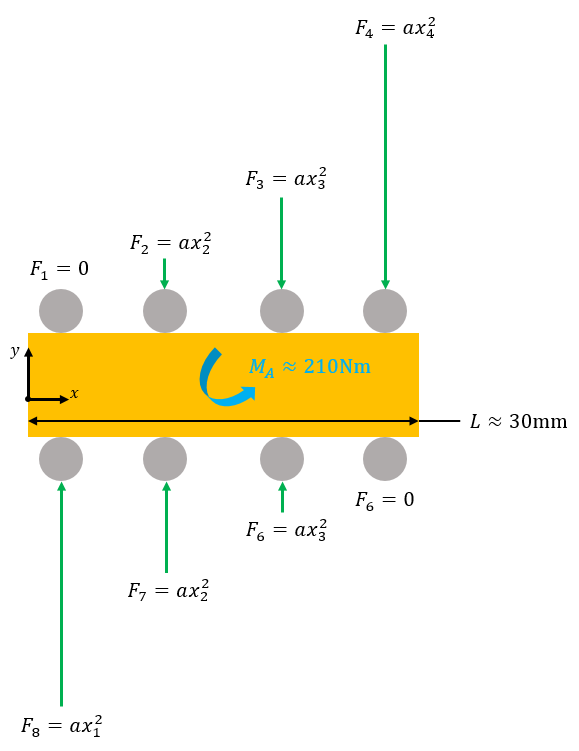
The forces acting on the detector can be found using the model shown below. The front half rolls in a track, and the back half is supported by the mechanism I am designing. The system is 2nd order indeterminate, and instead of just doing the hand calcs, I decided to make a full symbolic solver capable of solving any (solvable) beam system.
Symbolic Beam Solver
All you need to pass in is the moment equations that describe the beam, and boundary conditions, and it does the rest. This way solving indeterminate beams using superposition is lightning fast, literally 45 seconds instead of maybe 30 minutes, and of course no risk of algebra mistakes solving for constants.
A sub-set of the functions used in the code are hyperlinked here (gitHub):
- solveAndSubBeamConsts: Main solver function.
- buildBeamEqns: Takes moment functions and integrates them to produce displacement and angle functions. Uses a global variable to keep track of integration constants “C_n” for multiple functions in a script.
- constructBoundConds: Takes the displacement and angle functions and builds a set of simultaneous equations to be used in conjunction with continuity equations to resolve integration constants
- constructContConds: Takes displacement and angle functions and constructs simultaneous equations to be used in conjunction with boundary equations to resolve integration constants
- newIntConst: function used to initialize and update global variable indexing symbolic integration constants.
Understanding the loads is important for obvious reasons like sizing components inside the mechanism. A less obvious issues stems from the frictional interaction between the expanding service cylinder and the mechanism.
System Reference Surfaces and Thermal Cycles
Recall that keeping the service cylinder in contact with a known reference surface is essential in order to ensure the accuracy of the physics test data. Now imagine a thermal cycle from room temp to ~-50C (also recall the service cylinder has a negative CTE).
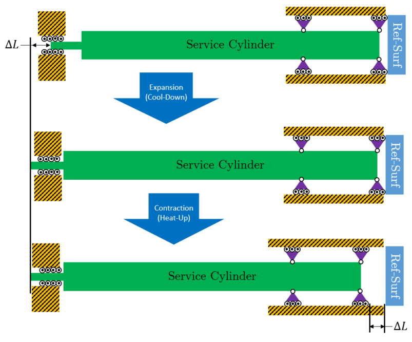
As the service cylinder cools down, it expands into the reference surface on the front end, and elongates axially on the back end. When the system heats up, the service cylinder will contract, but relative to what? The XYZ Slider equillibrates moments over a very small distance, versus the wheels (purple rollers in figure) which equillibrate moments over large distances, several millimeters compared to about a meter respectively.
This means the resulting reaction forces in the XYZ-Slider are considerably larger than at the wheels, and in turn the frictional forces are also much larger in the XYZ-Slider. All contractions take the path of least resistance, and as a result, the service cylinder would become effectively grounded relative to the XYZ-slider. That means the contractions are unilateral at the front end, leading to the service cylinder permanently contracting OFF of the reference surface, making all experimental data inaccurate.
The solution is likely obvious at this point, just place a bias spring inside the mechanism. The key is choosing a spring that will always defeat the worst case frictional forces in the the wheels and XYZ-slider but is not stiffer than the service cylinder itself. If this were the case, every unit the service cylinder attempted to expand would result in stress developing in the service cylinder as opposed to free expansion at the XYZ-slider.
Force Results
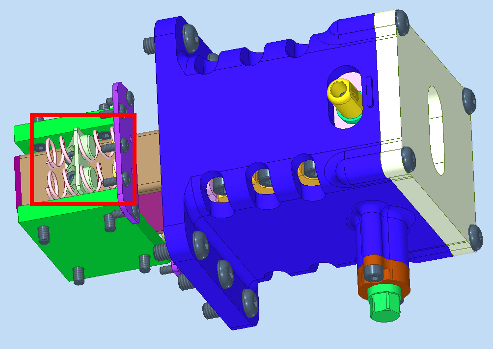
Below is a photo of the springs as well as the output of my beam symbolic solver (with some additional code), which solves for reaction forces using Euler Beam Theory and superposition constraint equations. This information gets written to a text file, so it can easily be sent to other engineers who may not have a MATLAB license.
---------------------WHEEL-SIDE SUPPORT REACTIONS---------------------
FORCE REACTION: 388.84N
MOMENT REACTION: 168.50Nm

-------------------(WHEEL-SIDE) PER WHEEL REACTIONS-------------------
LOW LOAD WHEEL REACTION: 62.96N
HIGH LOAD WHEEL REACTION: 131.46N

-----------------XYZ-MECHANISM-SIDE SUPPORT REACTIONS-----------------
AT MECHANISM TRANSVERSE LOAD: 491.84N
AT MECHANISM MOMENT LOAD: 168.50Nm
AT MECHANISM TRANSVERSE LOAD (W/ Kf: 1.25): 614.80N
AT MECHANISM MOMENT LOAD (W/ Kf: 1.25): 210.62Nm

--------------XYZ-MECHANISM-SIDE ROLLER FORCE/STRESS DATA--------------
APPROXIMATE STATIC LOAD RATING FROM EGIS DATASHEET (OVERALL BEARING): 120224.0N
PRELOAD AS A PERCENTAGE OF STATIC LOAD RATING (OVERALL BEARING): 1202.2N (1.0%)
NEGATIVE PHYSICAL OFFSET TO PRODUCE PRELOAD: XXX MICRONS
NORMAL FORCE AT BEARING ROLLER 1 -- BASED ON QUADRATIC FORCE DISTRIBUTION: 423.521N
NORMAL FORCE AT BEARING ROLLER 2 -- BASED ON QUADRATIC FORCE DISTRIBUTION: 1125.591N
NORMAL FORCE AT BEARING ROLLER 3 -- BASED ON QUADRATIC FORCE DISTRIBUTION: 3231.802N
NORMAL FORCE AT BEARING ROLLER 4 -- BASED ON QUADRATIC FORCE DISTRIBUTION: 6742.154N

------------------------ROLLING RESISTANCE DATA------------------------
WHEEL-SIDE ROLLING RESISTANCE (W/ Cr: 0.005): 1.94N
WHEEL-SIDE ROLLING RESISTANCE (W/ Cr: 0.005, W/ Kf: 1.25): 2.43N
XYZ-MECHANISM-SIDE ROLLING RESISTANCE (W/ Cr: 0.005): 115.23N
XYZ-MECHANISM-SIDE ROLLING RESISTANCE (W/ Cr: 0.005, W/ Kf: 1.25): 144.04N
TOTAL SERVICE CYLINDER ROLLING RESISTANCE (W/ Cr: 0.005, W/ Kf: 1.25): 146.47N
MINIMUM PER SPRING FORCE (W/ QTY: 4 SPRINGS W/ Cr: 0.005, W/ Kf: 1.25): 36.62N

Output file generated at: 21-Sep-2020 15:57:59
Current Directory: C:\Users\mns72\Documents\SC_BreathingMechanics\Analysis\PreloadSpringSizing
Spring Optimization and Selection
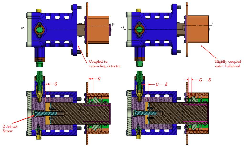
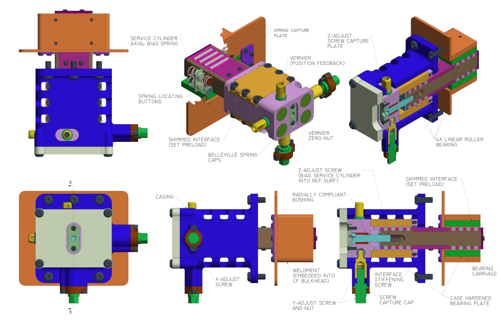
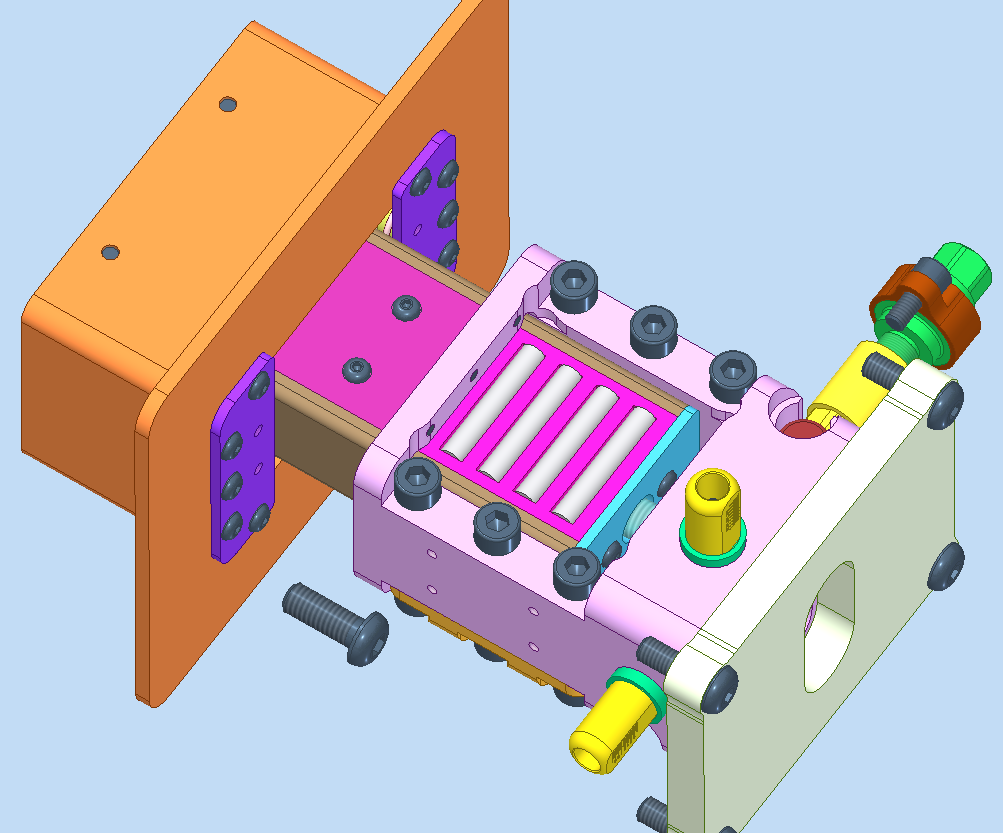
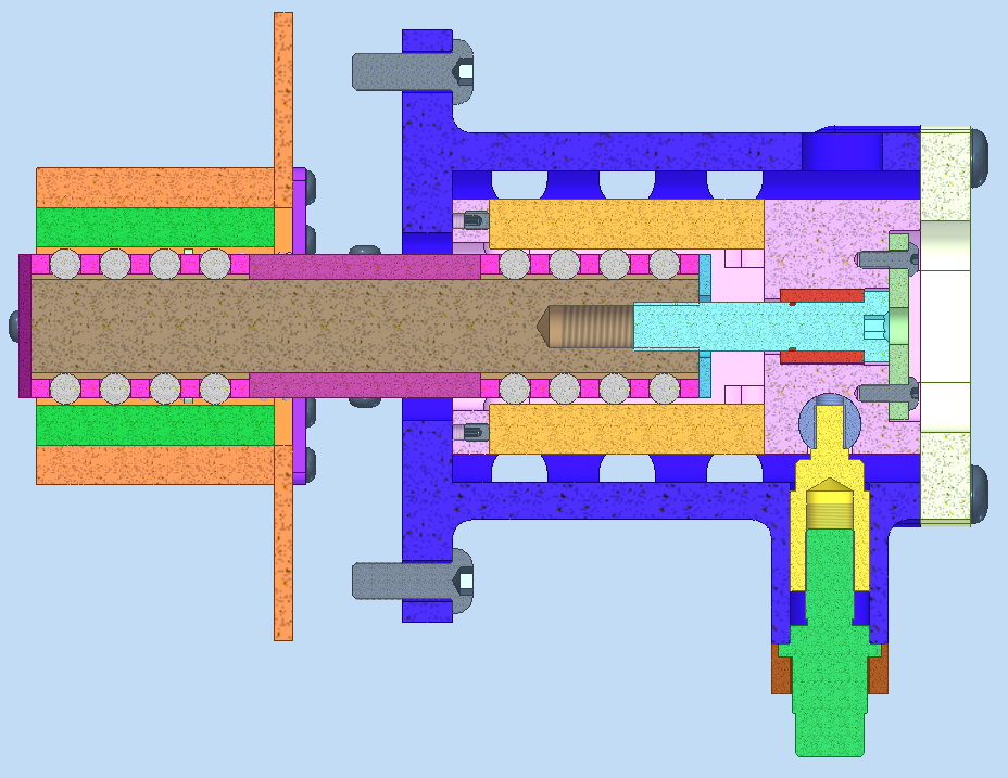
The process for setting the preload is shown above. The “Z-Adjust-Screw” is axially constrained by a shoulder and a capture plate. It is also threaded into the bearing carriage (brown). Rotating this screw cause the ball carriage to advance. The cool aspect of the orientation of the springs is that if during initial insertion (a lot more system detail would be required to understand this process which I can’t share), if for some reason the service cylinder is not in contact with the reference surface, advancing the screw will draw the service cylinder towards the reference surface until contact is made, and only then will additional force actually develop in the spring, ensuring there is always contact with the reference surface.
Something I’m currently working on is designing some kind of feedback to judge how much the spring has actually been compressed. At first glance a dial engraved into the Z-Adjust-Screw seems sufficient, but knowing how much rotation has gone into advancing the service cylinder into the reference service (if not in contact), and how much goes into actually compressing the spring is impossible. I am thinking about just having a tech measuring rolling torque as they are setting the preload and looking for a delta which would indicate a transition between rolling and spring compression regimes. Making some kind of physical feedback would be ideal as I’m not sure how repeatable the rolling torque measurement will be. The problem is that a technician will only be able to see the XYZ-Slider head on, rather looking directly at the back cover (key lime back plate above). Designing some kind of indicating gauge that isn’t overly complex, at least from a manufacturing standpoint, that can be viewed from that perspective is on the TODO list.
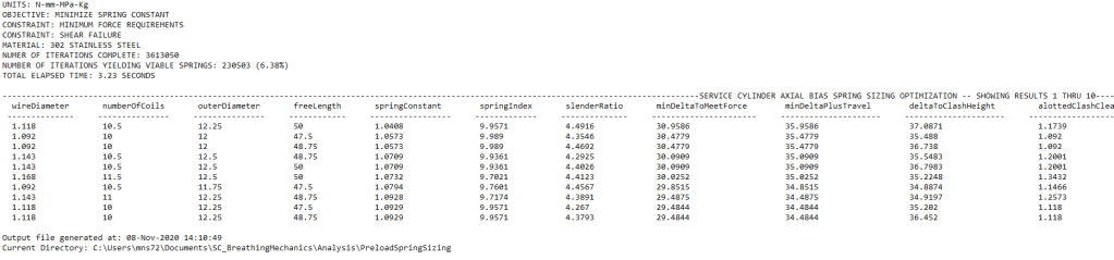
Choosing a spring was a little difficult. I’d like to avoid manufacturing one, considering we only need 10-20 total. At first I played around with an Excel calculator I made to design compression springs, kind of guess and checking, playing with different parameters. I quickly realized I couldn’t sleep at night knowing that was my process so I wrote a brute-force spring optimization script. The script output is shown below, and the script itself can be found -> SPRINGOPTIMIZER (GitHub). I wrote a table generating script nicely format data written to a text file which is not a built in function in MATLAB.
The optimization takes high and low limits for number of coils, outer diameter and free length. It takes material properties like the shear modulus, and functional requirements like minimum required force, and required travel. The resulting spring data is sorted to “minimize” the spring constant. Margins are pretty slim between defeating frictional force and attenuating axial expansion, so minimizing the amount of additional force developed in the spring (beyond minimum required preload) as it compresses became my driving optimization objective.
System Sensitivity to Mechanism Frictional Interactions
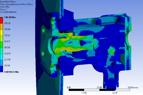
In an attempt to see just how sensitive the system is to frictional interaction at the XYZ-Slider, a very quick and dirty ANSYS sim was thrown together, and the axial displacement of a reference point at the XYZ-Slider was plotted against frictional force. I didn’t put a lot of effort into perfecting this analysis as the layup schedule isn’t finalized at this time. I made the assumption that all CF fibers are running along the longitudinal axis which is extremely conservative as it produces the largest amount of expansion and places the fibers in a buckling mode so they won’t be very stiff.

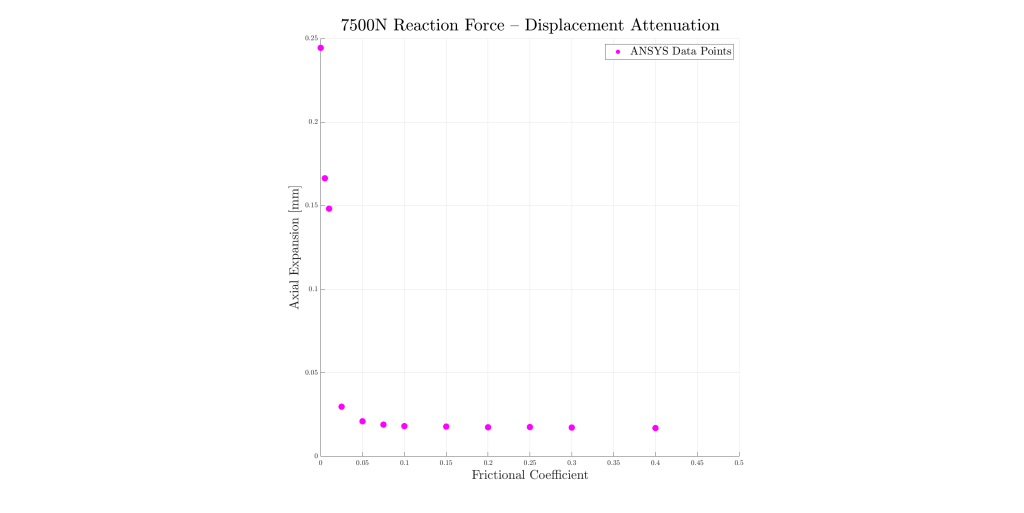
The system is is shown to be extremely sensitive to this frictional force. Even at a frictional coefficient of 0.1, the system is effectively grounded. An issue I had in the previous XYZ-Slider version design was over-estimating the service cylinder stiffness. Instead of rolling elements inside the mechanism, there was a lot of sliding contact which has a frictional coefficient several orders of magnitude higher than that of rolling. I assumed the service cylinders CF construction would make it extremely stiff, and it could overcome the sliding frictional interaction. The plot above is what led me to a re-design. You can however see some assembly drawings, ANSYS assembly results and more at at the bottom of this page.
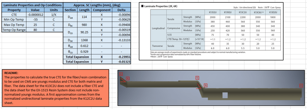
Evaluating exact service stiffness, and internal stress limits can’t happen until the CERN integration people select a fiber/matrix combination, and decide on the layup schedule. This is not an easy task as the radiation this system sees is higher than virtually anywhere on Earth, almost all polymer based matrix materials turn to dust. For now I’ll do my best to minimize resistance to expansion until more concrete numbers can be produced. I feel comfortable trusting this ANSYS at least as a baseline as it agrees with some Excel hand calcs I had done in months passed (shown below).
Quadratic Force Distribution and Contact Stress
A closest option to the spring my optimization produced was found online and ordered. The next task at hand was evaluating the linear bearings. At first I started looking at ball rollers, but the contact stresses associated with point contact scaled too quickly. I found a couple manufacturers who produce linear cylindrical roller bearings, and decided to deep dive.

The manufacturers datasheet/design guide was used to establish an initial baseline. I worried the atypical loading scenario for these bearings, especially the loading eccentricity, made some of the design equations pretty inaccurate , so I planned to do a legitimate investigation beyond the simple and very general use design equations. Recalling the applied moment of about 210Nm which was calculated in the results of a script shown above, we can evaluate the contact stress in the rollers. The discussion below takes only into consideration the forces induced by the applied moment as it by far dominates the response, but the code used to solve for forces also takes into consideration the transverse force and bearing preload.
The forces can only be solved for by first parameterizing them as a function of known location and a leading quadratic coefficient. A quadratic function was chosen to as a paramaterizing function with the hopes that it would capture the stiffening effects of the Hertzian contact-stress. In other words, the more force applied to a roller, the stiffer it gets, and in turn the high load rollers (near the resisting corners) turn out to be MUCH higher force rollers. The quadratic function is constructed under the assumption that the two corners opposite to the reacting corners carry zero load associated with applied moments.
If you’re interested you can look at the function that solves for the quadratic coefficient and uses here. Once those force values have been generated, they can be placed into a program called HertzWin, which evaluates contact stresses. I’d fully integrate all the functionality of this program into my primary design script so back end design changes can propagate down the line wherever relevant. For now this program will suffice.
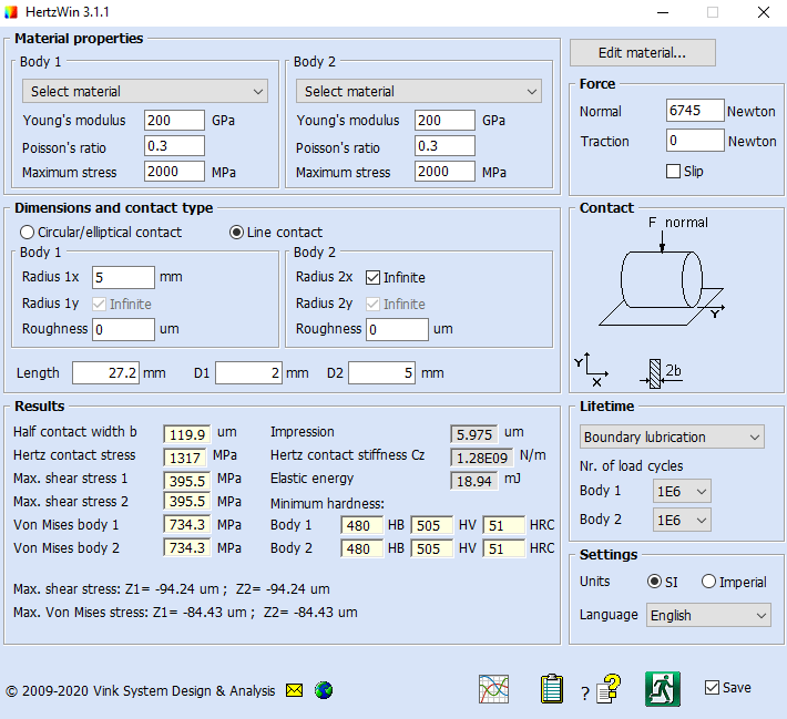
HertzWin Max Force Roller Results
The results show solid margin in shear which is the primary failure criteria for contact stress failure, at least at these virtually static rolling speeds. Sub-surface shear stress results in sub-surface cracks the propagate from repeated stress cycling. I do plan looking more deeply into fatigue life analysis, but the cycle count on the rollers is low enough that its almost certainly a non-issue. All surfaces will be either nitrided or conventionally case-hardened to ~60HRC, and considering the rollers only see a stress cycle once per cool down/heat up cycle and the large margin in shear, even if there was a thermal cycle per day, which is extremely conservative, the XYZ-Slider could operate for almost 2800 years before seeing 1E6 cycles, so we’re likely good on that front. Regardless, concrete numbers for hard limits are to be established, just not first priority as of right now.
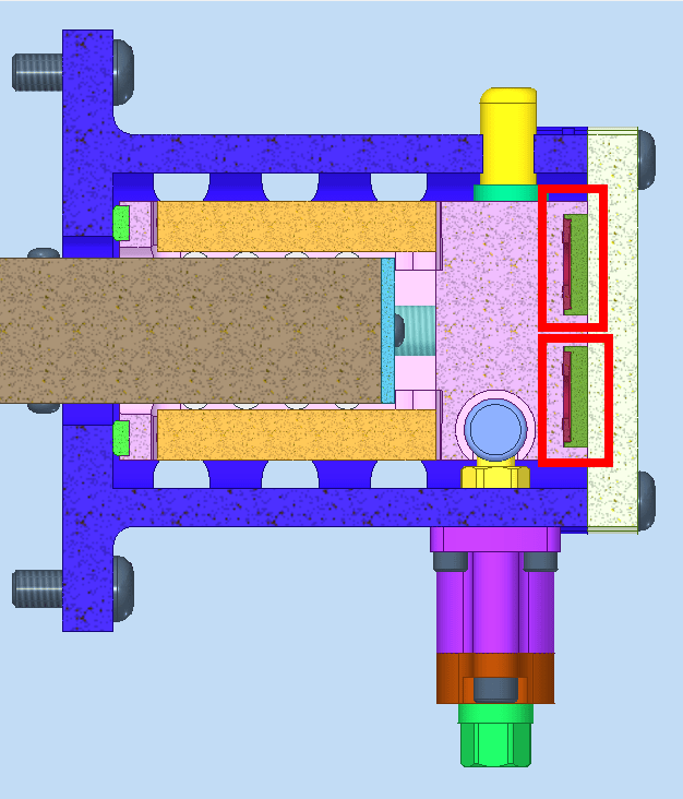
A small design change I’ve made while typing this is shown below. These components are now a second component. What might feel like the obvious big win is that material waste has been reduced dramatically. The much bigger win is the fact that the feature control on many features in the “actuation” group of components can be relieved quite a bit.
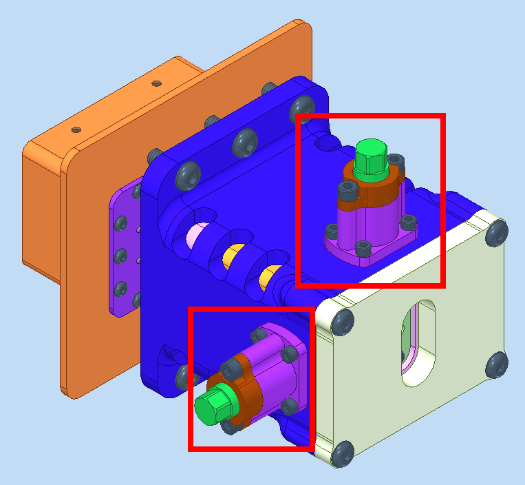
Looking at the older cross section (right), the fits at the yellow nut, the dark grey dowel pin it couples with and their respective bores is in the range of 10-20 microns as they are both bearing surfaces. So the linear distance to both of those bores would need to be controlled even more closely. If they don’t align perfectly, the mechanism will bind along its travel, or won’t fit together at all. This means the positional control on the bore that locates (yellow) and the bore that locates (grey), needs to be sub 10 microns. This change allows (grey) to locate where it likes, then after affixing (yellow) to (grey), the bearing bore that (yellow) travels in locates on yellow, and then is torqued down. The new section is shown below in the optimization discussion.
Statics Based Optimization
I’m currently working on a parametric optimization for some of the parameters shown below.
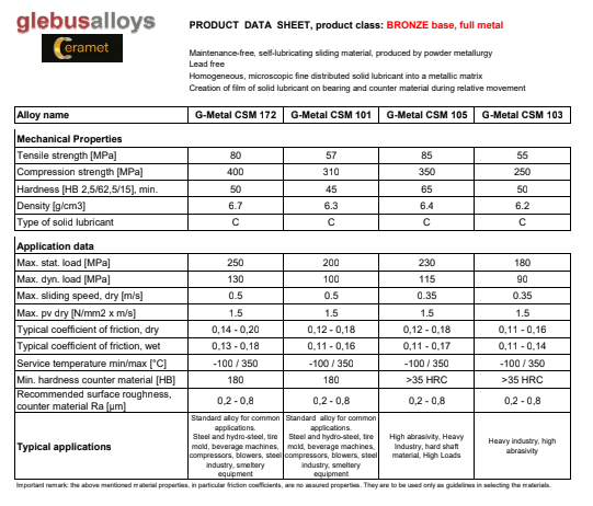
Also notice the contact pads at FR1 and FR2 (lime green). These are an addition I made a while ago but only just updated the CAD. They are a “fancy” self-lubricating sintered bronze material which excellent properties for this application. They can withstand upwards of 250MPa static contact stress while still freely sliding at a speed of 0.5 m/s and can run completely dry. Another additional benefit is the coefficient of friction is small like that of a lubricated surface, even when running dry. They also are not impregnated with any lubricious materials that will break down under the extremely high collider radiations. These were a necessary design choice as finding a chunk of material with these particular properties the size of (pink) would be both difficult and expensive. Also, from a tribological standpoint, having two discrete bearing pads is a much better design (and makes the analysis a tad easier).
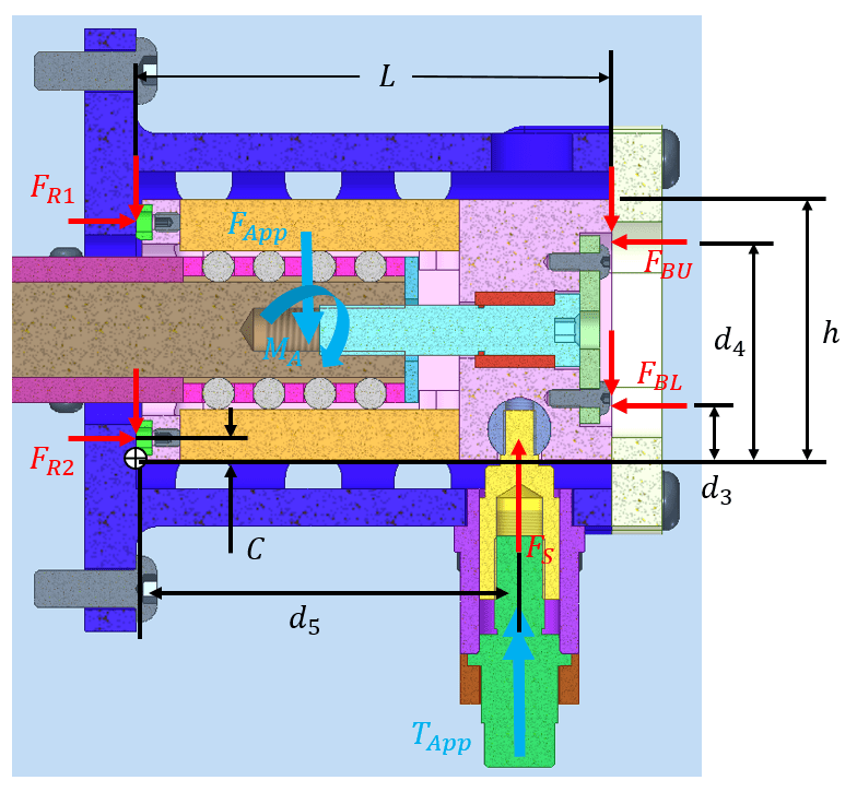
Anyway, back to the optimization. The model I’m evaluating is the point at which the screw force is at maximum, an instant before transitioning from static loading to actual translation. A description of parameters is given below
- F_BU: The upper belleville spring preload force. The bellevilles can’t be seen in this photo as they are slightly in and slightly out of the section (see below). This force is paired with an associated frictional force in the diagram.
- F_BL: The upper belleville spring preload force. The bellevilles can’t be seen in this photo (see below). This force is paired with an associated frictional force in the diagram.
- F_R2: Reaction force at the lower contact pad. This force is paired with an associated frictional force in the diagram.
- F_R1: Reaction force at the upper contact pad. This force is paired with an associated frictional force in the diagram.
- F_S: The force generated at the leadscrew by applying rotations to the exterior hex. This is in essence the actuation force. Its direction and magnitude can change based on lowering or raising.
- M_a, F_App: The static applied loads that were solved for above in the bearing section.
- L, h, d3, d4, d5: All geometric parameters whose locations define the different moment loads in the system.
In order for this thing to function, the (pink) component can never tip from screw actuation. Otherwise, instead of translation, the induced moment just results in rotation, and under the extreme loads, everything will bind. In other words, both lime green contact pads must actually be in contact during actuation. The objective of this optimization is: tune belleville forces and locations in order to react applied moment, while tuning other geometric parameters to ensure under those now existing belleville forces that under raising or lowering actuation, the sign of FR1 and FR2 never changes, which would imply loss of contact. Additionally, we’d like to minimize FBU and FBL which in turn minimizes the frictional interaction at all the services and in turn minimizes actuation torques, and the size of various components.
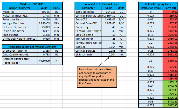
A “brute-force” for-loop-esque attempt was made for this optimization. The number and range of parameters necessitated the use of a real optimization algorithm. I’m currently in the process of setting this up using MATLAB’s optimization toolbox. Once I have those values, I have a script that generates belleville springs, similar to the one used for compression spring, and 4 bellevilles will be selected.
TODO List
- Designing a motor actuated test rig that can be loaded with a 210Nm moment and can be programmatically actuated in all axis to evaluate lifetime of the XYZ-Slider
- Finalize a reliable ANSYS model, this was completed for the previous version, there are some photos below. This is especially necessary to look into temperature delta effects on some of the more complex geometry components and bolted joints
- Many of the components have been sized using various scratch made spreadsheets shown below. I’m currently in the process of compiling various spreadsheets into a single script to establish associativity between all calculations for the XYZ-Slider and finalize low-level design requirements
- Re-design these capped bore features as a separate piece. This will ease manufacturing and material waste, but also allows for feature controls to be loosened considerably on certain dimensions.
- Developing a feedback design for the spring preload
- Designing locking features for X, Y, and Z
Photos of Older Versions