Description:
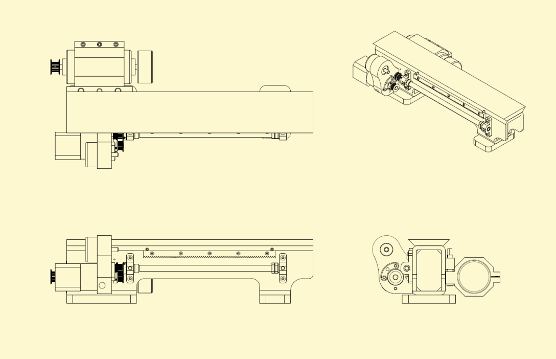
The bed is constructed from a stress-relieved steel tube. Steel reinforcements are welded into the tube to increase the machines stiffness. A cast iron way is bonded and fastened to the tube, acting as the main bed way of the machine. The tube is then filled with an epoxy granite. There are several accessories to be machined like:
- The leadscrew and bearing blocks
- Motor mount for the geared stepper powering the leadscrew and a rotary encoder to monitor the leadscrews speed relative to the spindle
- A modified stock rack gear
- A motor mount and belt tensioning assembly for the DC spindle drive motor
- Several plastic covers removed from the view above
Main Design and Manufacturing Considerations:
- Design bed to reduce displacement under loading conditions specific to a turning machine.
- Ensure that vibrations from normal operation are properly damped to reduce irregularities in work piece surface finish.
- Affix dovetail way to bed in such a way that the bed responds to loading as single cohesive beam.
- Ensure the machine base does not have a resonance frequency similar to those produced in turning machine operations.
- Ensure that all accessory features that interact with the carriage are positioned properly relative to the bed way in order to avoid binding or improper gear mesh.
- Produce a machine way with a small Rz value to mitigate rapid wear.
- Produce a machine way whose profile does not deviate from nominal more than .001″ over the 15″ length of the machine.
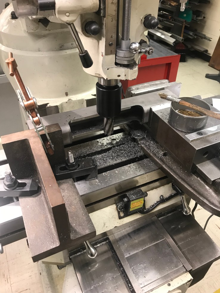
The first step on this journey is to cut away the central section of the lathe bed. I’ve had the hot rolled steel tube stress relieved to mitigate significant movement after the large asymmetric machining operation. I’m removing the center section not only for aesthetics but to open a space so I can torque the fasteners that will soon mount the cast iron way, so I can weld in some reinforcements to stiffen the bed, and because it’s easier to grind two small areas flat then it is to grind one large section.
I welded in the reinforcements and some feet and after a little more rough machining sent it off for a second stress relieving. I’ll finish grind the critical faces after this stress relief.


While waiting for the bed to get back from the stress-reliever, I machined the lead screw bearing blocks. You can see me reaming the bore for the sleeve bearings and rough machining the bearing block. I purposely machined both blocks as one piece and then split them not only for convenience, but to ensure the distance from the central bearing axis to the mating surface of the bearing housing would be nearly identical on both bearings. Any deviation on that dimension would result in series binding of the lead screw.


I trued the feet up after the final stress relieving cycle. I clamp the now co-planer feet to two angle plates first, then indicate across them. This reduces the risk of twisting or bending the part if the angle blocks are not co-planer.


I ground the feet first just so I could pull the part on and off the chuck when grinding the dovetail top surface and not run into issues down the road. I then ground the top surface of the bed that will mate with the cast iron way. I drilled the holes after the final stress-relief in case there was any series movement, there was a risk of losing the necessary precision in the hole locations and having two parts that no longer could be fastened together.
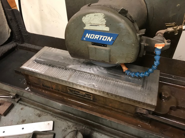
Because I cut the now .375″ way blank from an 1.250″ piece of continuous cast grey iron bar, there was a slight bow from some residual stress in the casting. I’d imagine this stress is a result of a temperature gradient from the exterior to interior surface of the casting through the cross section. The bow was ~.006″ as measured on the surface plate. It’s important to shim a thin part like this or the magnet chuck will pull the part flat, and then when released, it will return to its original bowed state. You can see the grinder is cutting on the high spot in the center.

Between grinding the top surface of the bed and bonding, I drilled all the holes for mounting the bearings and rack gear. This way I could use the top surface in it’s final state as a datum surface for all the other operations on the bed.
The bonding process was extremely nerve-racking so I couldn’t get many photos. Here is a photo of the cast iron bonded to the steel tube using DEVCON metalized epoxy which I chose specifically for its mechanical properties and it’s thermal expansion coefficient. There are also about 25 10-32 fasteners holding the whole works together. I shimmed the epoxy joint with .005″ shim stock hoping the epoxy will act as a damping layer between two metals with different vibration damping ratios.
PART 2
