Main Design and Manufacturing Considerations:
- The central axis of the spindle must be parallel to all faces on the bed dovetail way otherwise all parts would be turned tapered.
- The headstock must self align to the bed way.
- Reduce misalignment between both the front and rear bearing to prevent rapid wear on the bearings and reduce vibrations in the machine.
- Means of machining the housing bore and spindle diameter to a tolerance that only varies by ~.0007″
- A means of repeatable pre-loading of the bearings without any expensive, fancy equipment.
- Some type of reference feature on the spindle nose for accessories to be reliably mounted and ensure concentricity with the spindle.
- Means of manufacturing those reference features with <.0005″ axial and radial run-out.
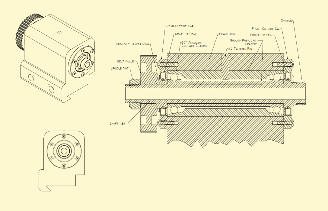
- Some way of reducing the ingress of metal chips and grit into the bearings while also serving to contain the lubricating oil/grease.
Starting the headstock machine was a daunting task. I had a relatively expensive 4.25″ square block of cast iron which I didn’t want to screw up. Once I was certain of the design I started thinking about what order of operations would result in a functional headstock. I had to decide if it would be easier to cut the dovetail profile in the headstock relative to the spindle bore, or vise versa. On a lathe, the spindle axis is typically the main datum, and things fall into place around it. I also knew I could shim the headstock in the vise after boring the hole.
I went with a straight through hole spindle housing like is found on Hardinge lathes. In order to pre-load the duplex pair angular contact bearings, the inner and outer racer are pulled co-planer which makes a pre-loading scheme quite easy to design. If I were to turn two individual shouldered bearing seats in the housing, it would not only complicate machining both seats concentric with one another resulting in slight bearing misalignment, but it would also be difficult to measure the distance between shoulder faces and in turn machine an inner bearing pre-load spacer. Instead, a spacer for the inner and outer race can be turn separately and match ground to the exact same width.


Spinning the entire headstock in the 4 jaw chuck was nerve racking to say the least. There was a huge imbalance and I had to run the machine on nearly the slowest speed. You can see on the right, the tool post grinder with an extension and a 36 grit grinding stone. In order to sneak up on the final diameter, I left the bore undersized by ~.002″ and then ground the bore with a tool post grinder. This gave me a lot more control over the size, and honestly on an old warn out Clausing like I was using, there was a bit of feel involved as I couldn’t rely solely on the dials. The final result gave a bearing the could gently be tapped in with a brass hammer, but would not go by hand, which is the exact fit I was hoping for as the Js7 fit required for the dynamic inner race load for a bearing this size is 9T~17L (microns).
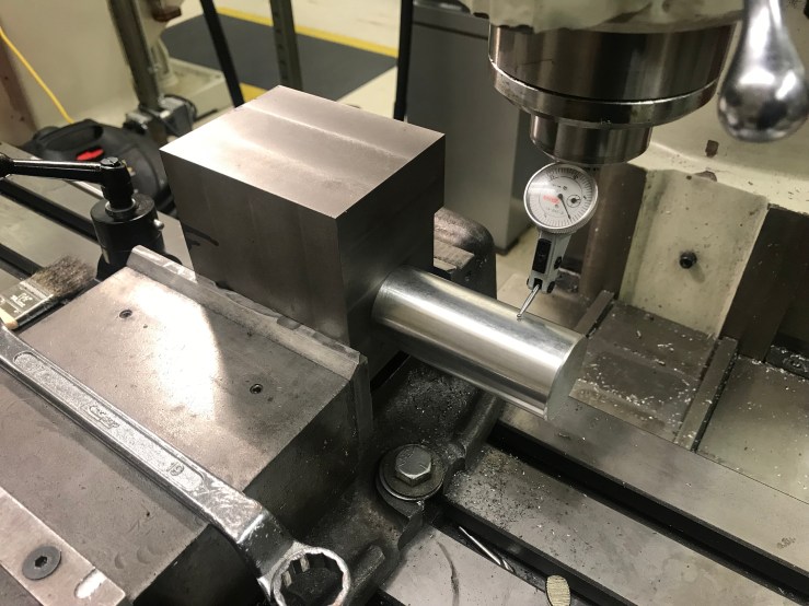
I turned up a 8 inch length of aluminum to a very close fit with the bore, and then tapered the back end with a coarse file so it would self locate in the bearing bore. I could then put the headstock in the vise and indicate on the top and side of this round bar to ensure that the dovetail profile would be relatively parallel to the spindle axis.
Although I got at most ~.0004″ deviation along the four inch length, I realized I’ll be able to true up the spindle reference surfaces as it rotates in it’s bearings with a simple fixture so perfection wasn’t essential here, I’ll touch on that later.

I cut the dovetail in both the headstock and the way clamp as an assembly for obvious reasons. In order for necessary clamp load to be achieved by torquing the fasteners, there can be no extra space between the vertical face on the clamp that mates with the headstock. The joint would be much too compliant and the clamp would just flex instead of clamping rigidly. Instead of trying to machine dovetail to the perfect size to prevent this condition, I purposely oversized it by ~.010″. I can then lightly torque the fasteners and check the resulting gap and make a “crush” shim from brass that will fit into the gap and ensure that the joint is rigid and required clamping load is achieved.
 Although I haven’t machined the spindle or any of the other inner workings, and I may be getting ahead of myself, this is the fixture for truing the spindle in it’s own bearings relative to the dovetail. The “dovetail block” gets pushed against the reference rail of the surface grinder, and the registration diameter and face on the spindle just passed the threads can be trued up by simultaneously radial and side wheel grinding.
