This fixture was supposed to much more complicated, with movement in 3 axis and a vacuum system to locate and secure the ASICS to be bonded to the flex-circuit. Because electrical tests needed to move forward to design was simplified significantly in order to reduce manufacturing time.


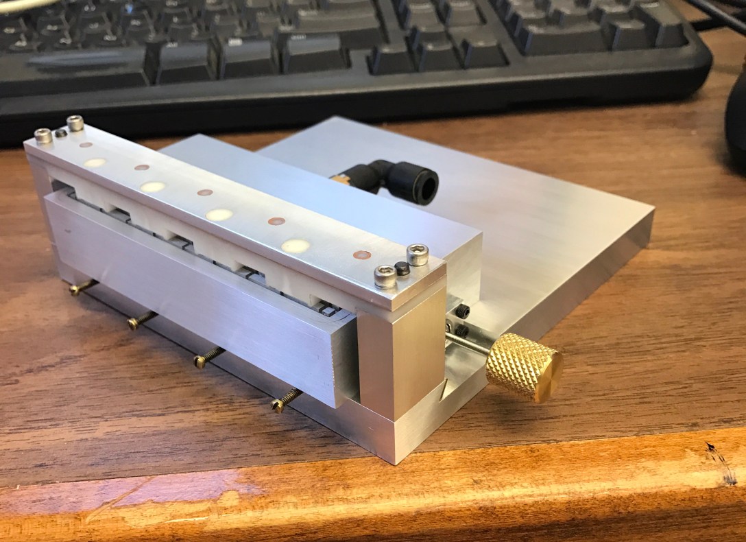
The fixture consisted of a vacuum chuck that would be moved in a single axis via a lead screw and a dovetail way. On the right the dovetail vacuum chuck has been cut, and the vacuum chamber milled. The tabs in the center reduce localized deformation of the cover plate under vacuum.


After the epoxy for the cover cured, the top surface was fly cut and stoned to a very fine finish which would ensure a proper vacuum seal. Vacuum channels were cut to give the vacuum a larger cross sectional area than through holes alone which will give the chuck more holding strength.


On the left, the bridge that the ASIC’s register with the maintain accurate position relative to the flex-circuit. On the right I’m measuring co-planarity of the ASIC pockets relative to the bridge mating surface.


The finished pocket with the flex-circuit in place relying on dowel pins for positioning. The gold plating are the bond pads where the ASICS are to be bonded. Wire bonds are then made from those ASIC’s to the flex-circuit.
