Conception
In mid-2019, I started contemplating the possibility of an arm constructed primarily of plastic joints, composite links, and high-performance exotic gearboxes. Over the summer, I began experimenting with different overall topologies and DOF joints. To be made from plastic, the geometry of the joints likely had to be smooth and continuous to prevent stress focusing and local yielding of the higher load carrying joints. Combinations of different DOF joint locations and different link orientations were compared. Partially mimicking commercially available robotic arms, it was decided the current joint topology provides the highest level of manipulability and configurability.
Plastic Material Selection
The selection process for a structural plastic was not very difficult, within less than a week the decision was made. The selection pool was greatly reduced by the fact that we can not machine impregnated plastic in Emerson Machine Shop. Top contenders were PEEK, Ultem 1000, Acetal, and Nylon. At first glance, Nylon seemed to be a very good choice. However, lack of stiffness, and it’s moisture absorption and dimensional instability problems quickly rendered it unusable. PEEK is four times more costly than Ultem and eleven times more costly than Acetal. The only real advantage PEEK has over Ultem is that it is just slightly stiffer (5 to 10 percent), maintains its structural properties at higher temperatures, and is more chemical resistant. The two latter properties provide no appeal in this particular application so PEEK also was removed from the list of possibilities. Finally, Ultem beat out Acetal because of it’s dimensional stability, it’s stiffness to cost ratio, and the fact that we found a manufacturer who was willing to send us twice as much as we needed for manufacture.
Carbon Fiber Analysis
The carbon fiber links were analyzed using the ANSYS “Simple Layered Section” analysis tool. Composite and fiber type/strength were quickly narrowed down to high modulus (HM) for its cost to stiffness ratio and it’s bending oriented layup. The number of t echnical decisions was also drastically reduced by the lack of product availability and technical data for lower end tubing.
The two tube shoulder to elbow link was chosen as it became apparent that designing smooth and continuous “tilt” joint bodies that were not unnecessarily bulky or extremely difficult to manufacture was made much easier with smaller diameter tubes. The two tube planar orientation was chosen as it excellently carries in plane bending moments which comprised over ninety percent of the loading in the region of use. Out of plane moments and loads comprise a small fraction of the loading, but exist nonetheless. The two tube orientation performs well under these conditions as they are so small relatively speaking. 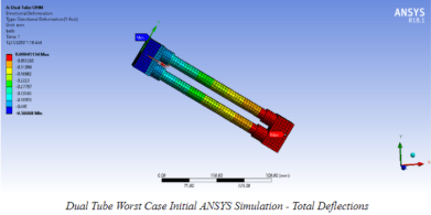
The single-tube upper arm link was chosen for similar reasons. The design and manufacture of “rotate” joints meeting the aforementioned requirements was made much easier use larger diameter tubes. The large diameter tube is a better performer under general loading as it’s geometry its cross section is axisymmetric. The loading conditions in this region of the arm are much more general and a round tube conveniently a better option.
Preliminary ANSYS simulations of the top 3 tube options and rudimentary Ultem joints under extreme worst case conservative loading produced deflections between six and twenty thousandths and stress margins in Ultem of around eight to ten. Linearizing the relationship between length and deflections leads to an approximate deflection at the end effector of about .060” worst case loading with arm fully extended horizontally. This approximation is extremely conservative as the points of extremely high strains are located in the Ultem bulk local to the significantly oversimplified boundary conditions. The results gave sufficient insight into the feasibility of this design, and the true design process began.
Better Understand Loading
The first step was to better model and understand the loading to establish more refined estimates for analysis and torque requirements. This was done using a  relatively simple Matlab script that modelled the arm as serial connection of line bodies and point masses. The hope is to expand this code in the Spring to fully model the arm in 3D and approximate full 3D static and inertial loads. Some code examples are shown below. The masses required for loading were conservatively approximated from either previous year’s mass values or values from a rudimentary CAD model.

Motor Selection
From there a spreadsheet was made to size motors based on static and start-up loads using a range of plausible gear reductions and reasonable motor mass. Taking into consideration our partnership with Maxon Motors, and their extensive line of pancake/flat series motors, the motor selection quickly narrowed. These motors were specifically selected as the performance metrics they are optimized for are direct requirements of a robust robotic arm. They also have an extremely low axial profile which reduces the odds of damaging the motors from accidental bumping. Motors were selected based on their weight and operating torque thresholds. We expect extremely intermittent use and are still operating well below the danger threshold of any of the motors ranging between thirty to sixty percent stall torque under the worst case expected loading.
Torque Transmission Feature
At this time, torque transmission features were also compared and a d-shaft was chosen for its ease of manufacture, it’s simple to analyze stress state, and relative strength and reliability. Fastener or clamp style couplings we’re not chosen as assembly and integration with prevailing joint designs became incredibly difficult.
The fit requirements between the torque shaft feature and its corresponding pocket must be extremely tight, as lost motion and in turn positional inaccuracies may develop. All the effort put into producing a backlash free gearbox would be for null. Another concern is the rapid degradation of shaft pocket features due to large impact velocities resulting from excessive shaft to pocket clearances. It was decided these features will be machined using a plunge EDM located in Clark Machine Shop as the profile tolerance band on that machine is well under a thousandth of an inch. This process decision was also a significant contributor to the choice of a d-shaft as plunge electrodes would have to be manufactured to produce the shaft pockets.
Gearbox Selection
Gearing down is used to describe some means of mechanically exchanging speed and torque, typically through the use of gears. As the minimization of mass and envelope are fundamental to the success of the arm, a gearbox with an extremely high specific reduction (reduction per unit volume) is essential. We also aim to minimize inertial loads which entails some control scheme for accelerations but also minimizing max joint or link velocity. It would appear we have the optimal conditions for exploiting the previously mentioned relationship, we wan’t a lot of torque, and we specifically do not want anything moving too quickly.
An issue that is inherent to conventional means of gearing down is backlash. Backlash is the play or clearance between interacting mechanical components. Backlash is a requirement in conventional gears or power transmitting screws as the interacting components would otherwise bind against themselves. Backlash results in “lost motion” in the gear train, in other words, the input moves “x” degrees but the output only moves “𝛽(x-𝛿)”, where 𝛿 is some deviation in rotation and 𝛽 is a proportionality constant that is unique to the kinematic relationship between the specific geartrain’s input and output.
We wish to use the built in motor feedback for positioning, and if as a result of backlash, the computer knows the motor has spun 5 degrees, but the joint itself has only moved some unpredictable lesser amount, we can no longer rely on the feedback from the motor and now no longer are certain of the position of any point on the arm in space. This error has a compounding effect, so small errors eventually accumulate beyond our allowable tolerance. Using a reduction scheme that makes no effort to reduce backlash or even remove it completely means adding significant non-essential design and manufacturing complexity.
Two types of unconventional gearing are ubiquitous in robotics, the cycloidal drive and the Strain Wave Gearbox (SWG) as they both produce enormous reductions and effectively zero backlash. During the initial design phase, both of these gearboxes were analysed. The decision was made to move forward with the design and manufacture of harmonic drive gearboxes to be used in all of the joints. Our sub-par analysis experience at the time also led us to believe the cycloidal drive could not survive the worst case loading conditions. The SWG was chosen not only for lack of any other real option, but also because of its zero net radial loading, large number of teeth engaged, no sliding contact (the tooth traverses both radially and tangentially), no high speed eccentric masses, and higher specific reduction. Designs were developed by Benjamin over several months to a final state. He spent what is likely to be hundreds of hours optimizing tooth geometry and running ANSYS simulations. Manufacturing complexity dominated the risk space and ultimately led to the demise of the SWG. 
The SWG reduction happens to be a function of tooth count, so in order to obtain the necessary reduction in a reasonable envelope, the teeth are made to be as small as possible. Although the teeth were not conventional involute teeth, there involute equivalents would have a module of about .35. The tooth itself was designed to be about .015” tall. A litany of GD&T control was required to ensure the gearbox did not bind against itself. If the pitch diameter location or tooth profile deviated in the realm of even a thousandth positive, the gearbox would not fix together as there would be interference, and if the deviations were too large negatively, the gearbox would ratchet. Because of the ornate tooth shape and the feature scale, a wire-EDM machine was the only manufacturing choice. The design also required that several hundred sub three millimeter shouldered pins be machined which would have literally consumed the entirety of JanMan manufacturing time. There were also concerns with flex cup fatigue life.
The project was eventually cancelled after two different EDM shops tried their best to help us manufacture these at a reasonable price and just couldn’t make the numbers work. Paying full price for wire-EDMing would consume a large portion of the entire on-rover budget, so it was a non-option.
*** A QUICK ASIDE: The following paragraph is included from completeness from my original documentation. That being said, the vast majority of the problems associated with the arm final product stem from the gearbox and its attributes. These issues are discussed here.***
It just so happens that one of my sub-team members is now operating in ANSYS on a level that rivals a true industry analyst. He decided to re-run the cycloidal drive, now certain of the correct process. It was found that a gearbox constructed with 7075 aluminum passes loading with significant margin. He initially had contact on a single tooth instead of several which reflects the physical system. The gears do require being sent out for type II hard anodization. Other than that, the benefits far outweigh the costs. We can machine all the components in-house, which allows us to thoroughly vet the manufacturing process at little to no expense. The total number of parts has gone from dozens per SWG to about 5 per cycloidal, most of which can be mass manufactured if setup properly in the CNC. The total manufacturing cost has also been reduced from some uncertain number, likely in the thousands, to at most 300 dollars. The envelope is also identical which meant a nearly one to one swap in our joint joint assemblies from SWG to cycloidal.
