
Finally, the design of the joints themselves can be discussed. When designing the joints, the necessity of a “joint template”, for lack of a better term, was apparent. Joint template describes a standardized set of features that are to exist on all the joints, only to be modified slightly based on each particular joint. The components of this set are:
Primary Structural Components
Components (7) , (8), (14), and (15) are examples of the primary structural components for the second rotate. They carry all the external load, and the configuration of parts and features have been strategically chosen to isolate the gearbox internals from
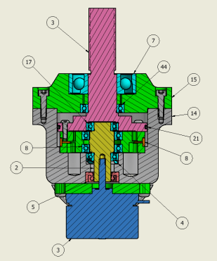
external loading. They are also designed to distribute bending moments at the output shaft in the form of radial and thrust loads. How this is done can be seen on the free body diagram above. The load path from external loading passes through the bearings, the the aluminum cover plate (15) and into the casement (14). Someone might argue that the entire casement might see deformation whose dependence on vertical position would induce some internal loads that are seen by the gearbox internals. It turns out that the high percentage strains are actually rotations about the mounting shafts of the rotates, and so the internal stress in the region
of the gearbox is quite low. It’s worth noting that the upper bearing pictured above is an angular contact bearing (shown as radial) as there is a net thrust that would otherwise cause separation the the bearing races or axially loading of gearbox components. 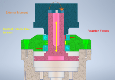
ANSYS simulations of all the individual joint assemblies were run to verify the integrity of the joints but also to verify that per design they actually do isolate the internals from excessive internal loading. It also has been verified in ANSYS that, under the correct pre-tension in pink output shaft with the tube coupling, there is zero gapping on the tensile bending side and in turn no bending stress’ development in the extended section of the output shaft. The associated deformations are orders of magnitude smaller as to be expected and the output shaft’s size can be made increasingly smaller as it only carries internal tension resulting from axial preload. Sadly
Concentricity Enforcement
What is essential is that concentricity between the gearbox internals is enforced. Rather, there are features chosen to ensure that critical components can not deviate very far from a nominal concentricity or positional condition. If not, either the gearbox will lock against itself, it will have significant backlash, or the joint as a whole will be un-assemblable due to physical interference. In the “Joint Template” figure, the red lines designate surfaces that either strategically locate parts, or show interfaces where concentricity is critical to functionality. Almost every cylindrical surface acts in one way or another to locate and enforce concentricity between critical components. There are some manufacturing difficulties associated with this in the close tolerancing of several parts, but precision components are inherent to a precision finished product.
Gearbox
(See “brh68 End of Semester Report”)
Sealing
The joint internals must operate in a clean and lubricated environment. This implies that we must prevent the ingress of dirt and particulates and the leakage of lubrication at temperature as its viscosity decreases. It is also important to isolate certain electronics inside the joints from grease, primarily the slip ring on the third rotate. This is done via two dynamic seals, (5) and (21). The input shaft has a spring energized rotary shaft seal (5) and the output has a large diameter standard o-ring for sealing (21). The choice of sealing measures stems from the relative shaft speeds, ease of design, and importance of sealing.
The input shaft is rotating in excess of 4500 RPM. The surface footage at the shaft periphery would quickly destroy the less than ideal o-ring rotary seal used for the output, where as the rotary seals are designed for sealing at high SFM. The rotary shaft seal is likely the simplest and most reliable rotary sealing method, relatively speaking. For high viscosity grease it was an obvious choice. It’s crucial that this seal be leak free as excessive leakage could risk leaking into and damage the motor internals.
Quite frankly, in almost any other application the rotary o-ring seal is one of the worst sealing options available. It just so happens all the factors that make it suboptimal do not apply here. The o-ring seal was chosen because of its ease of design and the extremely low output shaft speed (10-20 RPM). Additionally, the operating pressure is likely less than 1.5 atmospheres, and the operation is intermittent. A low-profile (axially) means of sealing was achieved by simply adding a gland onto a surface that already existed. Compared to other non-o-ring sealing methods, bulky features would be necessary for the seal to act on.
Final Summary
To summarize, the accumulation of these features in all the joints should result in an extremely stiff, and virtually backlash free arm, and allow us to implement inverse kinematics. Utilizing an inverse kinematic control scheme allows for the easy, quick, and intuitive end effector control that we have already deemed essential. This allows for movement locked to an axis, a plane, a circular arc, or a planned path between two points in space.
The arm as of right now is coming in at between seven and eight kilograms. This is well above our initial hope of five-and-a-half to six-and-a-half estimate. There were some design challenges we didn’t foresee. The decision was made that we valued manipulability more than mass savings and so a trade off was made. This is still a significant mass reduction compared to previous iterations 10 to 11 kilogram total mass. The total arm cost is approximately $1,400 to $1,500.
We also hope to experiment with and attach strain gauges to the carbon fiber links provide feedback in a pinned or overloaded condition and automatically kill motor power under the “danger zone” conditions. Long term we would like to use strain gauge data to predict deflections in the arm under loading and account for them on the control side. It’s also worth noting that the arm can rotate over the rover and fold up on itself to reduce impulse loading and risk of bumping damage while not in operation.
